2.2. CREATING GEOMETRY
Daylight simulations involve the mathematical interaction of rays (representing light) and surfaces (representing physical objects). Before running a simulation, you must specify the physical elements of a scene using surfaces defined in Rhino or Grasshopper. These may include Extrusions, Surfaces, Meshes, and/or Boundary Representations (Breps).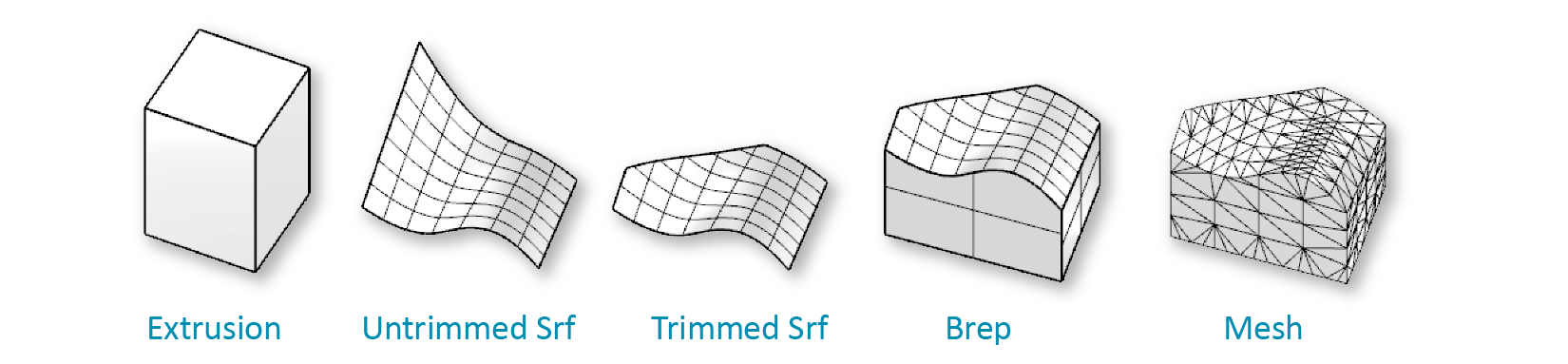
Acceptable input geometry types
2.2.1. LEVEL OF DETAIL
Although you may be tempted to include as much geometric detail as possible in your daylight simulations to maximize realism, be aware that added complexity increases run times, and does not always lead to more accurate results. In general, you should account for details that substantially impact the amount of light entering or reflected within a space. These may include blinds, curtain-wall mullions, or the thickness of a punched opening — but probably not minutiae like the drawer handles of a desk. If known, exterior elements such as neighboring buildings should be included as well, but here simple extrusions with appropriate materials should suffice.
2.2.2. LAYER STRUCTURE
Keeping a well-organized layer structure is an important part of modeling in any CAD environment. If you model geometric elements in Rhino (rather than algorithmically in Grasshopper), you should place objects of different materials on different layers. This allows easy material assignment using the DIVA-for-Rhino toolbar, and offers a convenient structure for referencing groups of objects from Grasshopper.
[TODO: good practice example]